Chris Arriaga


Skate Brake
The Skate Brake was a design project for a UCSB design course. The goal was to create a mechanism that could stop a runaway skateboard as quickly and efficiently as possible. The design consisted of a CNC machined body which housed the electronics including a Trinket, Power Boost module and RF remote control receiver. It also housed the AA battery pack as well as a small Lithium Ion battery. The machined brake arm was powered by a servo motor. The final product was able to stop a skateboard moving at approximately 10 FPS in under 2 seconds.
Torque Coupling
The idea behind the torque coupling challenge was to create a two-piece coupling consisting of a male and female part which could withstand the highest amount of torque possible before failure. The constraints for the challenge were that each piece had to machined from a 2 x 2 x 1-inch piece of FR 7120 polyurethane. Each block must be faced down to 1.95” x 1.95” x 0.95” and the outer diameter of the desired coupling must not be any larger than 1.8” while the base must be at least 0.2” high in order to fit into the fixture. Also, there must be a hole bored through each piece with a diameter of 0.501/0.499 in order to accommodate the torque wrench. Finally, once the design has been chosen and drawings have been created, it is necessary to perform analysis in order to estimate the torque that the coupling will be able to undergo before failure.
After some research, I decided to create a coupling that mimicked a Torx head screw. From my own experience, Torx screws are extremely strong and offer a variety of interlocking positions in which the bit can fit into the screw so my design would not be limited to only one interlocking position. Additional considerations went to the fact that the Torx head shape does not have any sharp angles or corners which would act like points of stress concentration. The smooth, rounded edges would allow for an easy fit while spreading the forces out throughout its geometry.


Once the coupling was modeled, I performed an FEA analysis within Solidworks in order to see how the forces were distributed within my design as well as estimate the torque at which failure would occur. This analysis was completed by modeling the base of the coupling as a fixed point, unable to move, and then applying a torque to the bored hole and top surface. Based on the analysis, it is estimated that the coupling would fail at approximately 70 lbf.in. While I am confident in my design, this estimate may not be entirely accurate due to the fact that I needed to input the material into Solidworks and the polyurethanes characteristics were slightly different than those values which could be entered into Solidworks.


The final step in the coupling challenge was to create the toolpaths and use a CNC mill to machine the coupling. In order to complete this, the toolpaths were created from the model using HSM in Solidworks. For each piece, the top was first faced down 0.05” in order to meet the requirements of a 0.95” height. Next, the shape of Torx shape was cut out of the parts using adaptive clearing toolpath. For the female part, the circular shape was cut out using Adaptive clearing as well, and finally the holes were created by boring. In order to achieve the desired 1.95” x 1.95” size and simplify the facing process, the pieces were attached to a wood wasteboard with double sided tape. This allowed me to cut out the entire piece without any worries of damaging the bit or having to use any sort of clamping or vice to hold the workpiece in place and it would be ok if the bit hit the wood surface. By using this technique, I was able to eliminate the need to rotate the workpiece in order to get the sides machined to the correct length


Automated Flash Cutter
This was a sponsored project by Strand Products Inc. They had an Ewald Flash Cutter (below) which was used to cut small diameter cables ranging from 0.040" to 0.008". The current process was done by physically pulling the cables being measured out to length and then manually actuating the cutter.

Together with 4 other teammates we developed a fully automated system which allowed for the operator to input a length and quantity over a touchscreen interface. The system would then run automatically until the desired job was complete.


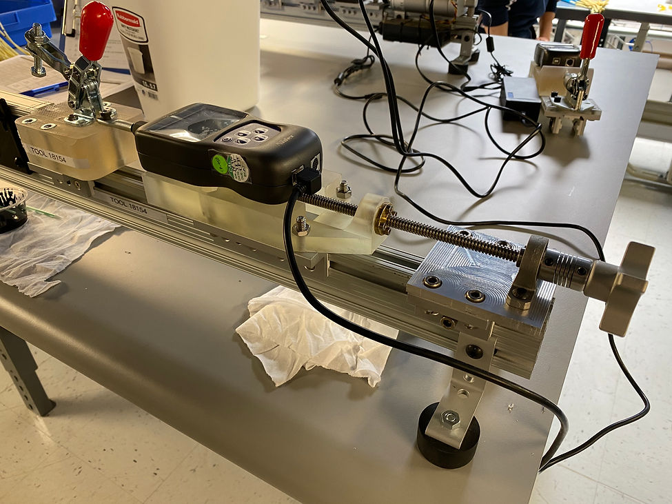
Cable Load Rail
This rail was created to pull cable assemblies tight to a specified load for measurements and affixing various components during assembly. I used an electronic force gauge to measure the exact load and it was able to be dialed to the precise load needed due to the lead screw design. The lead screw mount was CNC machined and the load cell and toggle clamp mounts were 3d printed. The entire system was then mounted onto an 8020 rail.
Automated Shear Cutter
This was an unfinished project. I created an automated shear wire cutter for cutting cables. All aluminum parts were cut on a CNC router. Cables would be fed through the wheels to the desired length via a stepper motor where the servo motor would then actuate the shear cutters.

Lego RoboRat
The lego RoboRat was for a robotic lab at UCSB. We had to design, build and program an automated "rat" capable of self navigating a course and collecting as much "cheese" as possible My partner and I won the competition.

